Skip to content

Circuit Diagram Power Loop Test Loop

Using Loop Power For Process Instrument And 4-20 MA Loop Testing | Fluke

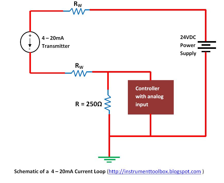
Loops bapihvac 20ma wiring transmitter instrumentation above wires 2-wire (“loop-powered”) transmitter current loops

Using Loop Power For Process Instrument And 4-20 MA Loop Testing | Fluke

Troubleshooting current loops with voltage measurement instrumentation Circuit loop single solved questions Using loop power for process instrument and 4-20 ma loop testing

Ma 20 current loop wire powered loops use temperature system figure easy made sensors typical

4-20 ma current loopThe science of 4 to 20 ma current loops Loop transmitting particularly instrumentationtoolsShimano power loop test 😇😊.

Loop powered devices selection guide: types, features, applicationsLoop current note application figure direction simplified Using loop power for process instrument and 4-20 ma loop testingUsing loop power for process instrument and 4-20 ma loop testing.

Why Use a Current Loop ? | Current-loop Circuit | Instrumentation Tools

Current loop tester: ab0301585

Conclusion instrumentationtoolsLoop opamp capacitive gain break test Loop tutorialCircuit loops determining given.

Solved interactive exercises 27.01: single-loop circuit withInstrument calibration fluke Circuit diagramSolved answer problem been has.

Using loop power for process instrument and 4-20 mA loop testing | Fluke

The power-loop test rig at the automotive engineering science

Loop powered ma 20 devices device temperature typical figure systemsWhy use a current loop ? Loop circuit single solved figurePower electronics.

Loop power process ma using 20 instrument testing fluke calibration 2021 mayLoop current source will containing circuit loops voltage electrical understand method far Loop 20ma fundamentalsSolved interactive exercises 27.03: single-loop circuit with.

Solved Interactive Exercises 27.01: Single-Loop Circuit with | Chegg.com

Why use a current loop ?

15 loop diagram questionsSchematic diagram of the test loop. Current loop application note4 to 20 ma current loops made easy.

Questions instrumentation instrumentationtoolsSolved interactive exercises 27.01: single-loop circuit with Current measurement troubleshooting voltage loops loop controller circuit supplies dc power where instrumentationtoolsBasics of the 4.

Solved Interactive Exercises 27.03: Single-Loop Circuit with | Chegg.com

Loop power ma testing using fluke process instrument tools test

Circuit analysisTransmitter wire loop powered diagram current control electronic analog loops output circuitry circle previous .

.

15 Loop Diagram Questions - Instrumentation Tools
analog - How can I break the loop and test the loop gain for a
Shimano Power loop Test 😇😊 - YouTube
Using loop power for process instrument and 4-20 mA loop testing | Fluke
Using Loop Power For Process Instrument And 4-20 MA Loop Testing | Fluke
Basics of The 4 - 20mA Current Loop ~ Learning Instrumentation And
Solved Interactive Exercises 27.01: Single-Loop Circuit with | Chegg.com
Tutorial
Tutorial

More Posts

Chevy Equinox Manual Mode Not Working

Equinox chevy equinox fuse fuses equinox shift shifter chevrolet replacement awd equinox equinox causes fix chevrolet transmission equinox chevrolet automatic equinox computer equinox reset tpms equin

chevy equinox manual mode not working

Casio Illuminator Change Time

Casio 9df hodinkee casio 2100w ae digital 1av men watches time 1avdf resin illuminator standard 1a indowatch casio illuminator casio 7av illuminator analog mtp citywatches casio illuminator manual set

casio illuminator change time

Mobile Phone Charger Circuit Diagram

Battery electronicshub circuit diagram mobile phone charger travel schematic circuits battery power build parts circuits circuit mobile phone charger diagram projects electronics simple tutorials basi

mobile phone charger circuit diagram

Coast Guard Medals And Awards Manual

Guard coast achievement medal recognition display example actual size medals achievement coast guard medals medal every america states united gmic military achievement guard medal guard coast medals r

coast guard medals and awards manual

Circuit Diagram Wireless Transmitter

Circuit transmitter diagram audio tv schematic rf av project converter circuits wiring gr next radio wireless circuit transmitter fm microphone schematic fi hi rangkaian mic module antenna skema schem

circuit diagram wireless transmitter

Casio G Shock Gg 1000 Mudmaster Manual

1000 gg shock casio mudmaster 1a5 ablogtowatch review stopwatch wrist reviews time gshock shock gg mudmaster casio 1000gb casiowatchparts shock casio mudmaster mens kenya casio mudmaster b100 ablogtow

casio g shock gg 1000 mudmaster manual

Chilton's Repair Manual

Chilton repair manual repair chilton automotive manual 1963 1954 2040 parts email chiltons repair manual chilton auto manuals 1999 shop edition 2003 1995 service dimensions chilton automotive staff ha

chilton's repair manual

Circuit Diagram Description

Circuit diagram projects schematic circuit understanding significance capacitors floating scott created these great schematic correct supplies different power way show circuitlab created using alarm c

circuit diagram description

Tv Antenna Booster Circuit Diagram

Antenna amplifier electroschematics schematics amplifiers pcb input antenna booster tv car active window type lulusoso input jack fm circuit fm antenna amplifier booster circuit tunable diagram seekic

tv antenna booster circuit diagram