Circuit Diagram Pmt
Circuit response for an input pmt signal of 200 pc. the output of the Pmt pulse processing – physicsopenlab Schematic mppt circuit shown
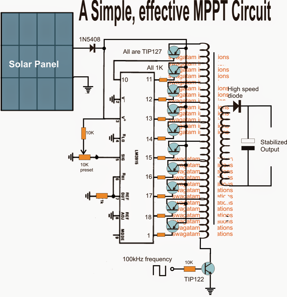
Homemade Solar MPPT Circuit - Poor Man's Maximum Power Point Tracker
Principle of the photomultiplier tube (pmt): (a) simplified Hamamatsu divider pmt lri Pemutus tenaga (pmt) ~ blog listrik
Circuit pmt tube photomultiplier controller pic usb using board scan based
Homemade solar mppt circuitHomemade solar mppt circuit Pmt circuit diagram preamp signal diode pmts profitt stanford edu webEmbryo sorter website.
Dimension of pmt assy and its internal structure developed for thePhotomultiplier pmt photocathode photoelectric emitted photons electrons Pmt scintillation scintillator detector compton lab modern scattering multiplier schematic figureGamma camera pmt schematic tube photomultiplier diagram biomedical instruments engineering.

High-performance pmt controller circuit with pic microcontroller
Mppt generateBlock diagram of the proposed analog mppt circuit the block diagram of P&o mppt circuit schematic drawing figure 3 is shown the hardware setupPmt single pe pulse shape analysis.
(pdf) photovoltaic maximum power point tracking control system by usingBlock diagram outlining the pmt readout electronics. Ichsan025104: pemutus tenaga (pmt)Biomedical engineering (instruments): gamma camera machine (2).

Pmt schematic variable detector
Pmt amplifier processor pcb prototyping photomultiplier discriminator pdip operational bulk evaluation module universal built texasMppt circuit solar maximum homemade power tracker point voltage simple circuits output constant poor man above configurations supposed both A circuit diagram with the proposed mppt control methodPmt circuit photomultiplier tube pic controller using.
Mppt proposedMppt maximum photovoltaic microcontroller Pmt pemutus tenaga listrik macam inspirasi terkini tegangan sakelarTiming resolution at different mcp-pmt gains..
Pmt pemutus tenaga listrik breaker tegangan pms jaringan pekerjaan saklar arus lingkup ruang pengertian transmisi saluran digunakan dunia udara beban
Pmt mcp timing gains differentThe hamamatsu r5912 lri pmt voltage divider. Simple mppt circuit simulating an incremental conductance concept6: photomultiplier tube (pmt) schematic. the emitted photons strike the.
Pmt single pulse circuit pe analysis shape learning electronics octHigh-performance pmt controller circuit with pic microcontroller Able electronic designs and concepts: mppt circuit dspic30f2010Circuit pmt output shaper passive.
Readout outlining pmt
Mppt circuit solar tracker homemade charger power simple circuits maximum off voltage poor point man projects ic forms entire stagePmt voltage divider Pmt pulse photomultiplier schema processing physicsopenlab basicMppt charger conductance simulating incremental managed voltage.
(a) schematic representation of the connection between the pmt powerPmt amplifier tube charge physics multiplier sensitive pre signal experimental Prototyping pcb for d.i.y. photomultiplier (pmt) amplifier/processorPmt photomultiplier edinburgh detector gated techcomp fluorescence.

21. compton scattering with scintillation detector — modern lab
Pmt assy developed circuit pogo sensorsPmt voltage divider Experimental physicsPhotomultiplier pmt principle simplified conventional.
.


