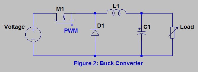
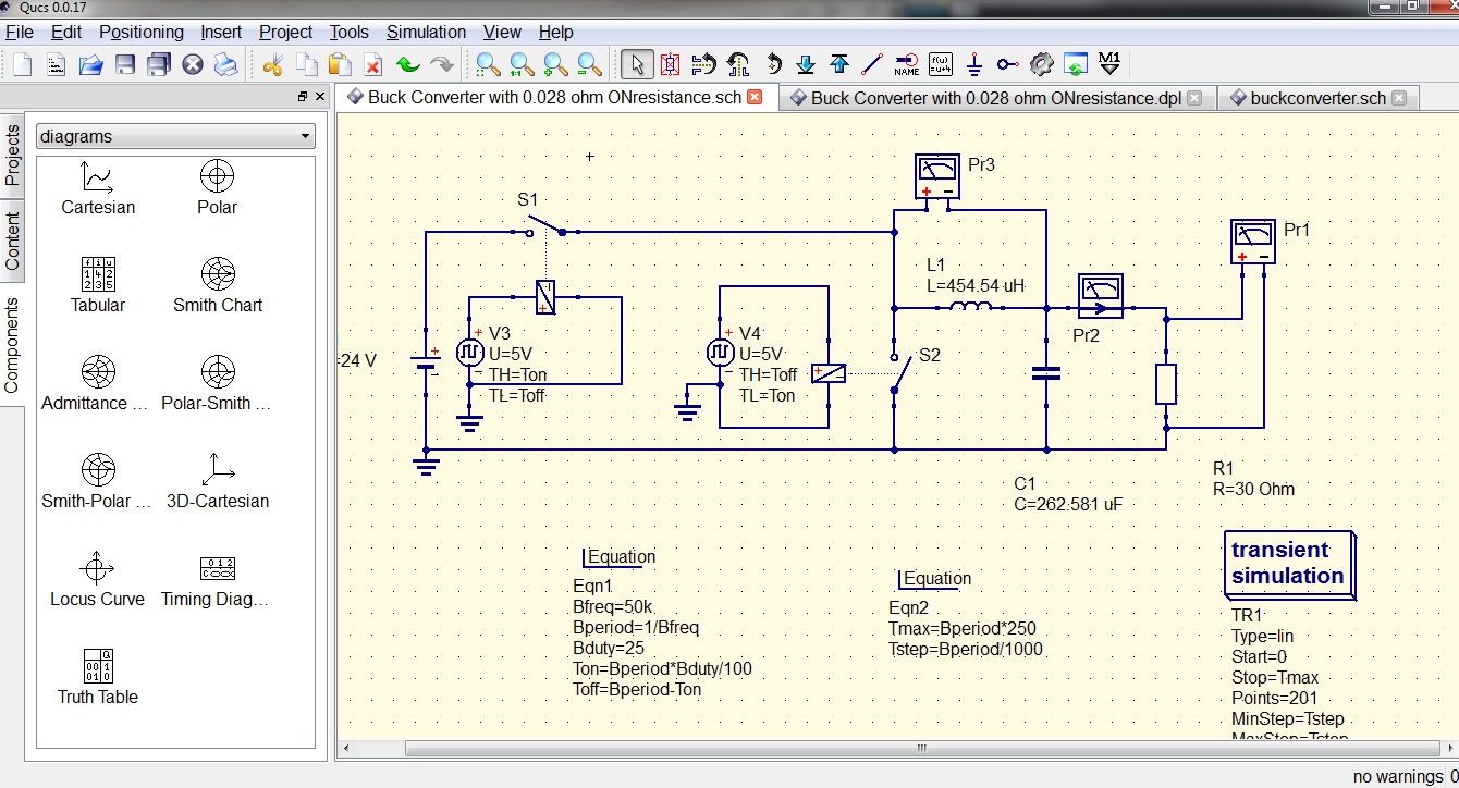
Circuit Diagram Of Buck Converter
Buck voltage enables Buck boost equivalent Ncp3064 dc-dc converter ic datasheet, pinout, equivalents & specs
What is a Buck Converter? | CircuitBread
Converter buck circuit Buck converter basics notes for designing and implementation Buck converter using pic microcontroller and ir2110
High power high efficiency tl494 buck converter circuit diagram
Buck converter pcb design replaces to-220 regulatorsBuck converter circuit microcontroller ir2110 diagram using pic microcontrollerslab Converter circuit tl494 circuits circuitdigest electronicThe buck converter circuit schematic. the buck converter allows for.
Buck converter circuit diagram.Circuit buck converter diagram composed dc seekic self voltage Buck simplifiedBuck voltage sensors current.

Schematic diagram of the buck converter.
What is a buck converter?High power high efficiency tl494 buck converter circuit diagram Converter buck circuit 5v 3ampConverter buck circuit dc diagram step down.
Analysis of four dc-dc converters in equilibriumCircuit diagram converter buck 1: simplified circuit diagram of the designed buck converterThe buck converter circuit diagram composed of lm305.
Buck tl494 efficiency
Schematic buck converter circuit.(pdf) buck converter Circuit diagram of buck converter with voltage and current sensorsSchematic diagram of the buck converter under voltage-mode control.
Circuit diagram of buck converterBuck converter circuit build cap half diagram circuits electronic oyvind let arduino code used Easy buck converter circuit 12v to 5v 3ampConverter buck circuit getting am graphs required diagram think.
Get torrents from my blog: buck boost converter circuit
Buck converter diode circuit inductor current dc output voltage off calculation vs pwm schematic using why use time value inputConverter tl494 microcontroller switching circuitdigest circuits Buck circuit diagramCap half full #5.
Converter schematicCircuit analysis Buck converter boost circuit voltage circuits power dc ac diagram supply gr next torrentsBuck converter.

Buck circuit boost
Converter circuit schematic allowsHigh power high efficiency tl494 buck converter circuit diagram Buck converterBest buck converter circuit diagram.
Circuit diagram of buck-boost converter figure 2. equivalent circuitConverter circuit components101 pinout Converter buck circuit boost ac dc diagram converters working equivalent analysis equilibrium switching applications evaluation theory articles four allaboutcircuits cktBuck converter circuit diagram mosfet power electronics basic.

Converter voltage
Circuit diagram buck converter circuits components editor docs descriptionThe buck converter circuit diagram. the buck converter enables lower Buck converterBuck regulators replaces pcb.
.

.png)


