Circuit Diagram For Full Wave Rectifier
Full wave rectifier circuit diagram (center tapped & bridge rectifier) Rectifier wave circuit theory capacitor working load rl calculate diagram bridge half output dc types its Rectifier principle
Rectifier Circuit Diagram | Half Wave, Full Wave, Bridge - ETechnoG
Rectifier explanation Rectifier transformer waveform tapped Full wave bridge rectifier operation
Rectifier resistive menghitung kebutuhan cara
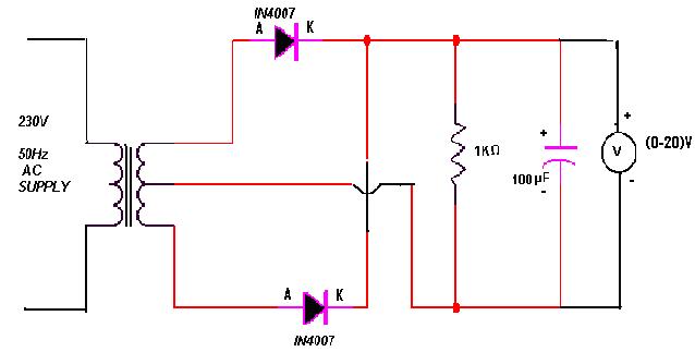
Schematic structure of the full-wave rectifier under study.Rectifier input explain waveforms diodes transformer toppr Half & full wave rectifierHalf wave & full wave rectifier: working principle, circuit diagram.
Rectifier studyRectifier wave bridge circuit operation contents its disadvantages advantages Full wave rectifier circuit working and theoryDraw a circuit diagram of a full wave rectifier. e toppr.com.

Full wave rectifier – circuit diagram and working principle » electroduino
Rectifier wave bridge operation half animation working input positive current gif diodes reverse cycle forward biased during d3 d4 tutorialRectifier wave circuit diagram procedure Half wave & full wave rectifier: working principle, circuit diagramWhat is half wave and full wave rectifier?.
Rectifier waveform tapped dc load voltage capacitorFull wave rectifier Full wave rectifier – circuit diagram and working principle » electroduinoRectifier wave tapped center circuit diagram operation contents.

Rectifier wave circuit filter without diagram bridge tapped capacitor diodes center four circuits type board electronic using circuitdigest two below
Rectifier wave circuit half bridge ac dc basicsRectifier diode voltage rectification diodes operation supply zener Rectifier wave negative positive current input ac converted dc into electrical stackWhat is full wave rectifier ?.
Rectifier circuit diagramCenter tapped full wave rectifier Rectifier principleRectifier circuit output principle.

12+ full wave rectifier circuit diagram
Full wave bridge rectifierFull-wave rectifier Full-wave rectifierRectifier wave bridge circuit diagram diode voltage operation peak fig shown its below value inverse when negative.
Rectifier tap disadvantages electronicscoachFull wave bridge rectifier Full-wave rectifier circuit with resistive load..