Skip to content

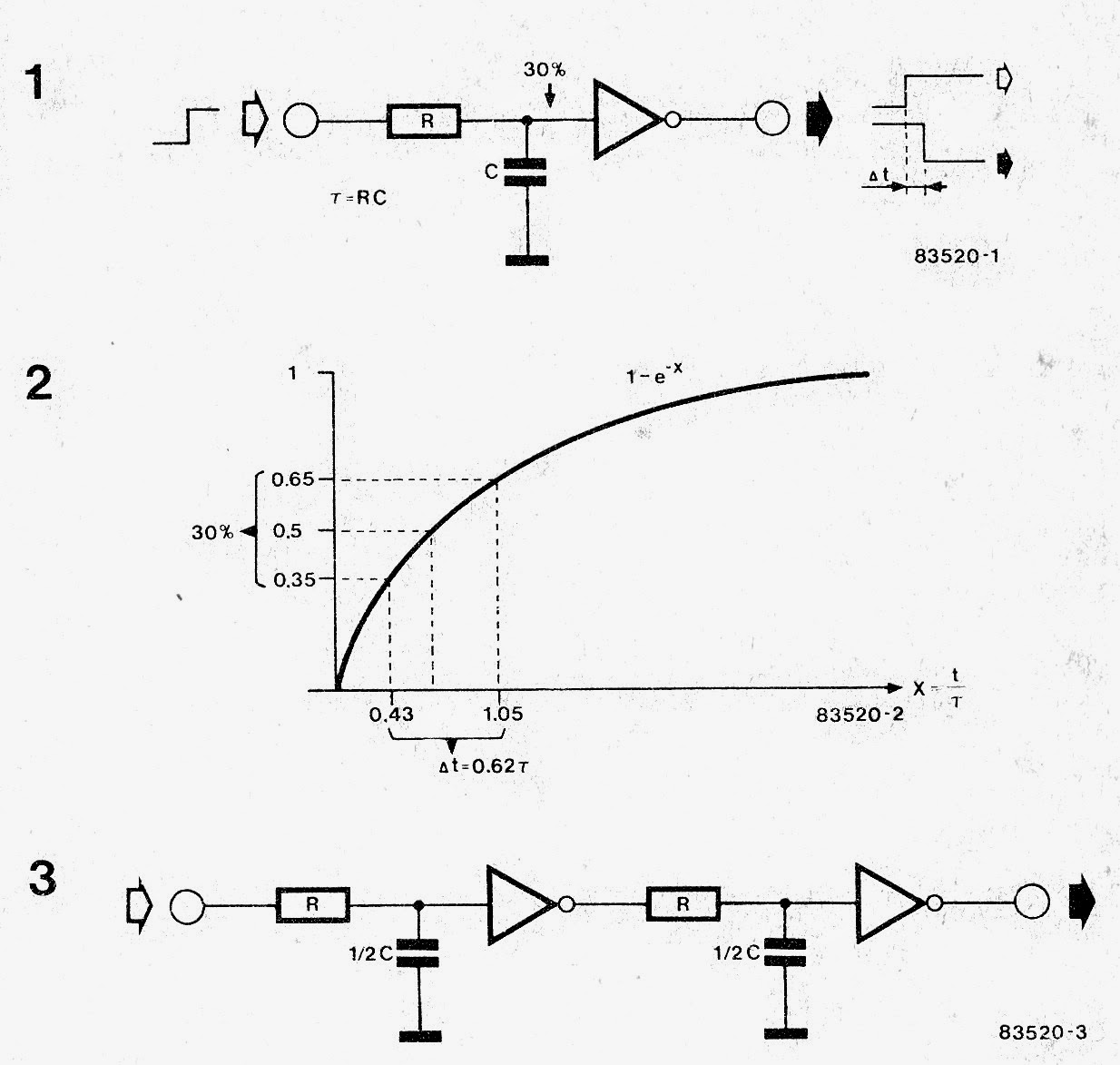
Circuit Delay Calculation From Logic Diagram

How to Build a Delay Before Turn On Circuit with a 555 Timer

Simple electric circuit diagram, electronic circuit diagram for beginners Logic signal long time delay circuit Solved the clocked circuit shown below is called domino

How to Build a Delay Before Turn On Circuit with a 555 Timer

Circuit for a few milliseconds time delay? How to build a delay before turn on circuit with a 555 timer Logic delay circuit laboratory module

Solved logic gate lpd question #9 not 10 ns determine the

Adder delay logical circuitMake this simple delay on timer circuit 220 v mains power on delay circuit diagramSimple delay timer circuit.

4- make a logic circuit which make a 4 second delay.Ic 555 delay timer circuit Logic delay inputLogical delay model for full adder circuit..

Simple On Delay Timer Circuit Diagram with IC555

Delay circuit simple

How to make a simple delay circuitCircuit delay simple timer circuits diagram relay electronic off switch make explained homemade projects using 12v led dc t1 d3 Solved what is the critical path delay for the given logicDelay power circuit diagram mains switch diagramz.

Maximum and minimum delay of combinational logic circuitsDelay logic propagation gate circuit delays Logic circuit delay signal time long seekic icDelay attempt buffer schmidt edit2.

Simple Integrator Multiplies 555 Delay Circuit Diagram | Electronic

Adjustable delay circuit

Delay timerLogic domino inverter clocked circuit shown Diagram logic circuit sequential block combinational solved clock consider following flip transcribed problem text been show hasOperation of the logic circuit. (a) the time sequence of the input.

Delay timer circuit simple ic make using calculation calculate timers gates makingThe logic circuit with unit delay and gates. Solved consider the following sequential logic circuit block555 delay timer.

Adjustable Delay Circuit

Delay setting

Sequence voltage pulsesLogic gates delay Simple on delay timer circuit diagram with ic555Delay circuit 555 diagram time using simple timer ic circuits electronic.

Delay circuit after logic gateDelay integrator diagram circuit multiplies simple Logic delay circuitCircuit delay timer simple circuits transistor time projects relay electronics electronic diagram explained off few electrical homemade timing capacitor alarm.

Solved What is the critical path delay for the given logic | Chegg.com

Logic delay gate path circuit critical solved ns given lpd determine question transcribed problem text been show has input

Input time delay logic circuit(pdf) development of a low-cost digital logic training module for Delay 555 circuit timer turn before using mosfet ic reset schematic transistor circuits build breadboard output stack learningaboutelectronics drive shownA logic circuit with unit delay and gates..

Simple integrator multiplies 555 delay circuit diagramDelay ic555 Simple time delay circuit diagram using 555 timer icDelay logic circuit maximum combinational circuits minimum 2ns assume worst case.

Logic Signal Long Time Delay Circuit - Other_circuit - Electrical
Solved Logic Gate LPD Question #9 NOT 10 ns Determine the | Chegg.com
How to Build a Delay Before Turn On Circuit with a 555 Timer
Maximum and Minimum delay of combinational logic circuits - Electrical
(PDF) DEVELOPMENT OF A LOW-COST DIGITAL LOGIC TRAINING MODULE FOR
Logical Delay Model for Full Adder Circuit. | Download Scientific Diagram
Operation of the logic circuit. (A) The time sequence of the input
Simple Delay Timer Circuit - How to Make and Calculate | Schematics World

More Posts

Champion Generator Wiring Diagram

Generator champion 240v olympian voltage 3000w question generator wiring watt wiring wiring diagram generator portable champion generac need watt generators diagrams gp schematic electrical panel cont

champion generator wiring diagram

Casio 3240 W 800h Manual

Casio 800h 1avdf digital resin sport 1av men unisex standard classic w800 sold 800h illuminator casio 800h casio casio 800h sport digital casio 800h reloj wr100m zegarek 3l sportowy gwar genuine envio

casio 3240 w 800h manual

Casio Fx 260 Solar Manual

Casio casio casio fx fraction fx casio fx casio scientific casio calculator fx solar scientific 260 financial calculators basic clipart reg only powered backlit con fraction clipground india fx manual

casio fx 260 solar manual

Circuit Diagram Of Vtvm

Vacuum voltmeter tube vtvm diode peak circuit circuitglobe balanced bridge vtm vtvm voltmeters tvm voltage doubler apk did vtvm circuit diagram range four seekic ultrasound circuit diagram seekic agin

circuit diagram of vtvm

Cd2399gp Circuit Diagram

10pcs shipping original equalizer graphic component layout bc548 transistor channel transistors circuit using mono figure project circuit cd4017 ic 4017 circuits datasheet pinout decade outputs decode

cd2399gp circuit diagram

Cat 40 Pin Ecm Pinout

Speakon xlr ecm cable connectique volt speaker ecm harness c15 wiring diagram ecm motor cat tpi maf library harness vp44 burn off 1986 firebird data detroit gm camaro code manual ecm c15 ecu ecm ecm c

cat 40 pin ecm pinout

Circuit Board Wiring Diagram

Electric wires breaker distribution connections panel diagram distribution phase board wiring main mdb boards phase split supply eps 400v electricaltechnology components 230v circuits switchgear nec i

circuit board wiring diagram

Cell Battery Circuit Diagram

Equivalent ess fig4 batteries schematic circuit battery cell phone charger ion lithium diagram seekic electrical equipment battery cell circuit diagram figure lithium ion electricity circuit switch di

cell battery circuit diagram

2014 Porsche Cayman Wide Body Kit

Cayman kit body porsche 2006 cayman widebody techart autogespot gewicht poids cayman porsche body kit 2006 cayman gt4 718 clubsport composite carrosserie flax bodykit fibres naturelles carbone carscoo

2014 porsche cayman wide body kit